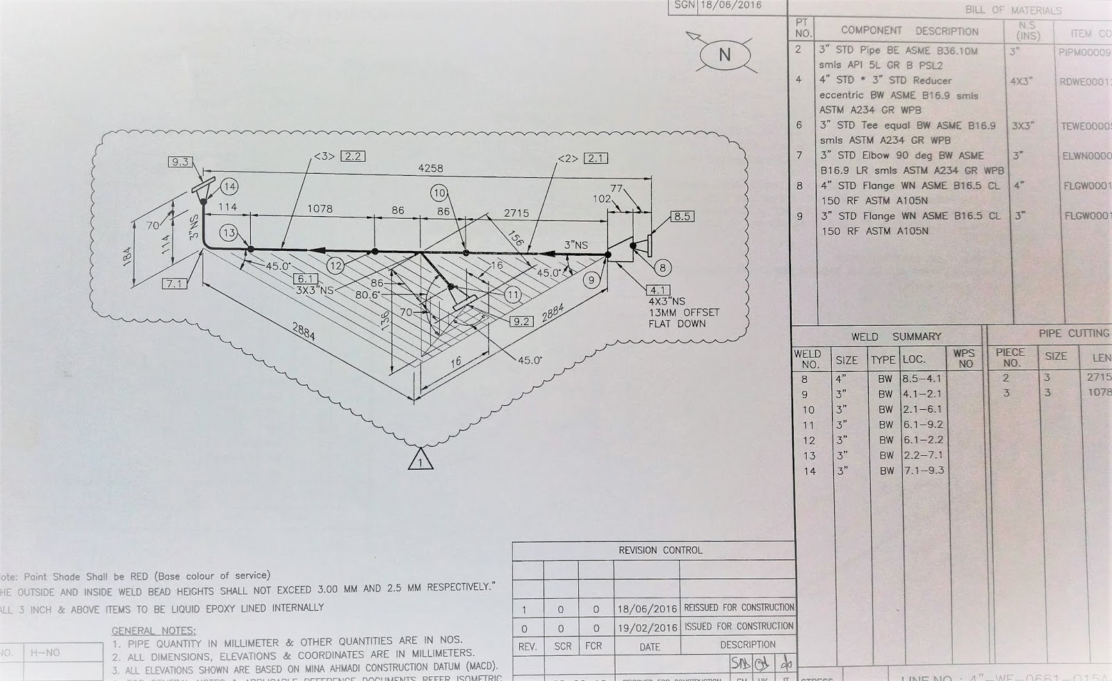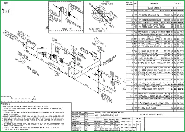

All the symbols are used as per Legend.

If the line is stress-critical, stress analysis results are incorporated.Special support like support from flange or welded supports details to be shown.Size and type of every valve/direction of operation.Give the details of the flange on the equipment if the specification is different from the connecting piping.Insulation class, Insulation thickness & Flow direction are indicated.Details and section identification match.Insulation requirements as per PEFS (P&ID). Requirements of upstream/downstream straight lengths.Location and identification of all instruments.Representation is correctly made in line with the standard symbols.Changes in the direction and angles of the line should be clearly shown.Equipment number & appearance on the isometric drawing.Coordinates of equipment against equipment layout.Design pressure, design temperature, test pressure, testing medium, radiography requirement, Heat treatment requirement, painting requirement, and internal coating requirement.Reference number of PEFS (P&ID), GA drawings, line numbers, the direction of flow, and insulation tracing.


A draft person ( piping designer/engineer) who knows to read the piping GA.Generally, isometrics are prepared/extracted by the design group.Isometric is also used to work out the exact MTO requirement.The main purpose of an isometric is to provide all information necessary for the fabrication and erection along with the bill of material required to do so.Piping isometrics are the three-dimensional representation of the line.


 0 kommentar(er)
